 Cyclope3D: a dedicated tool for
extracting 2D drawings from 3D data
Cyclope3D: a dedicated tool for
extracting 2D drawings from 3D data
Designed for and by drafters, architects, laser scanning and photogrammetry surveyors
A tool built on several years of client feedback and analysis of the deliverables on the market, which combines:
- Opening and analyzing 3D deliverables, to get to grips with the survey and make sure it meets the specifications.
- Automatic 2D drawing sheet generation, with no manual handling: georeferenced orthoimages, DXF/DWG drawings and PDF sheets.
- Several representations per view (texture, geometry, depth, solid areas, X-ray), overlaid in the drawing.
- Guided naming of folders, files and layers, derived from the project and view names.
- Customizable deliverables in the company's colors: orthoimage background, logo.
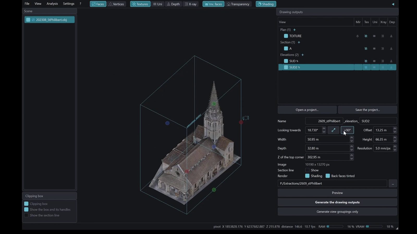
Use cases
Choosing the views and reviewing supplier deliverables
Placing and drawing the views, and their variants
Batch generation of the drawing outputs
The three steps
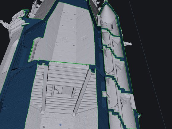 Step 1
Import and analysis
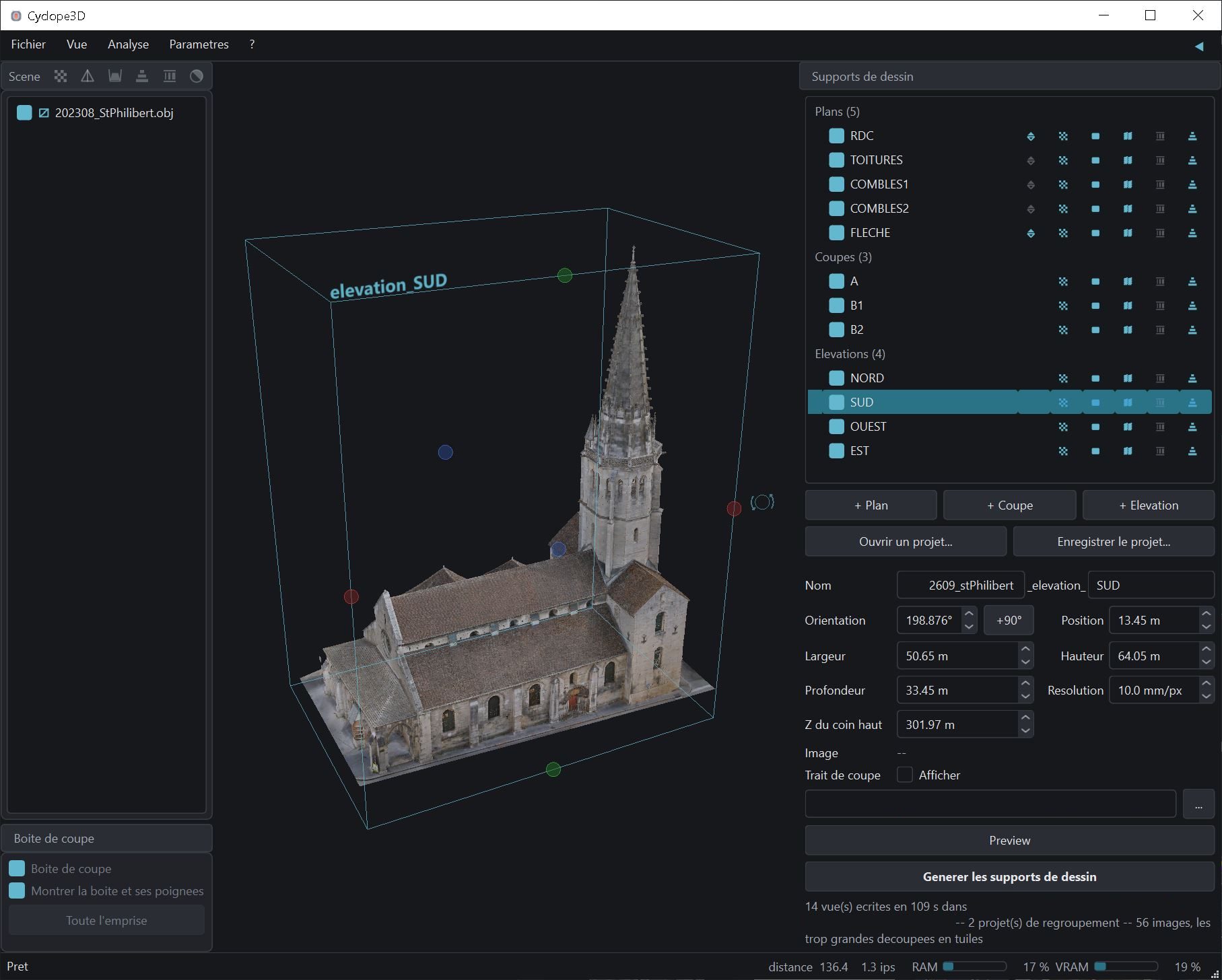
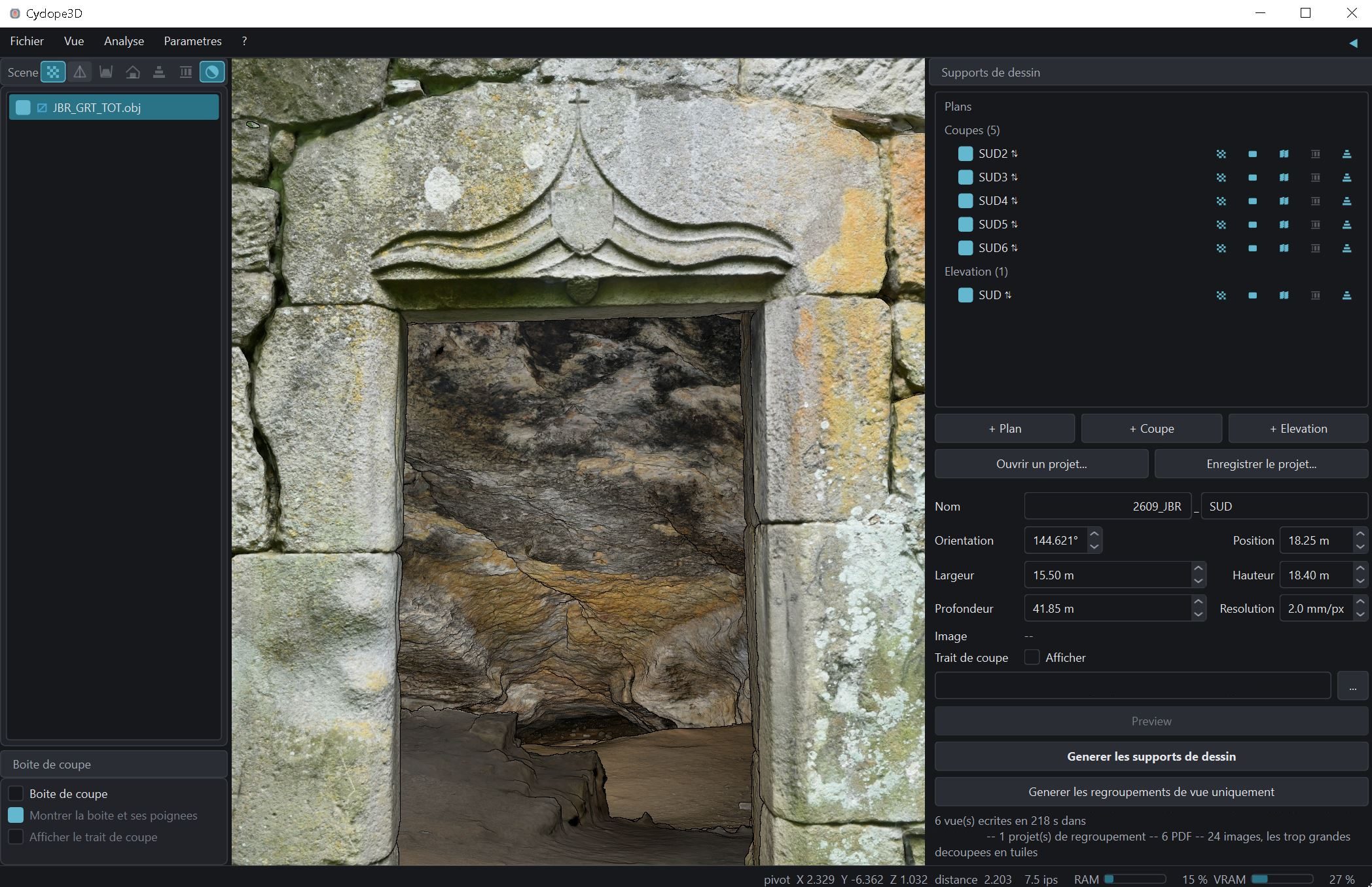
The survey opens as delivered, and is analyzed before extraction.
Step 1
Import and analysis
The survey opens as delivered, and is analyzed before extraction.
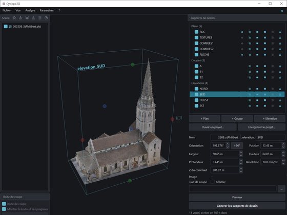 Step 2
Placing the views
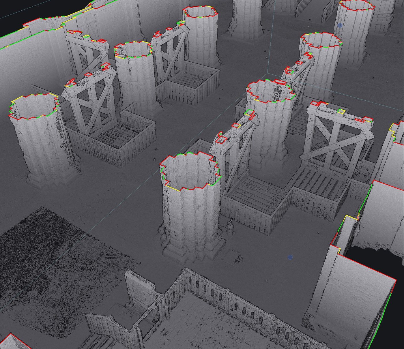
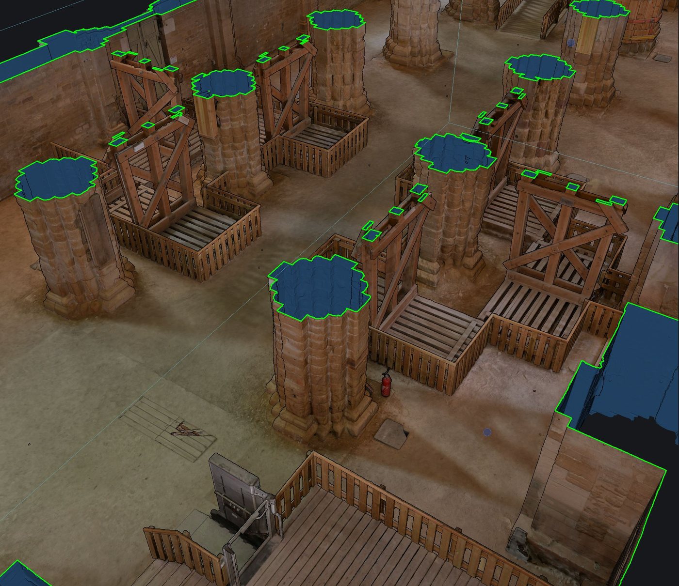
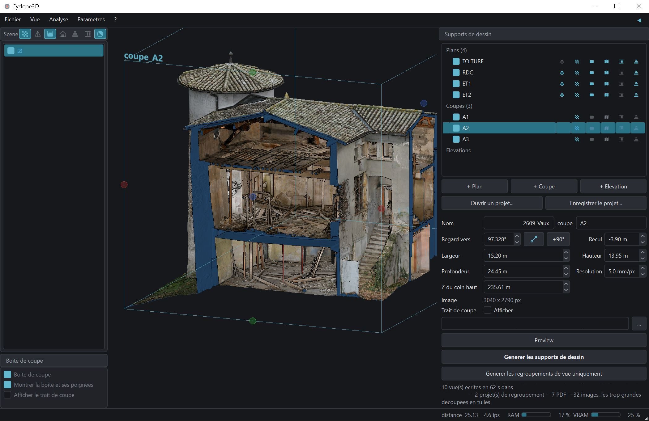
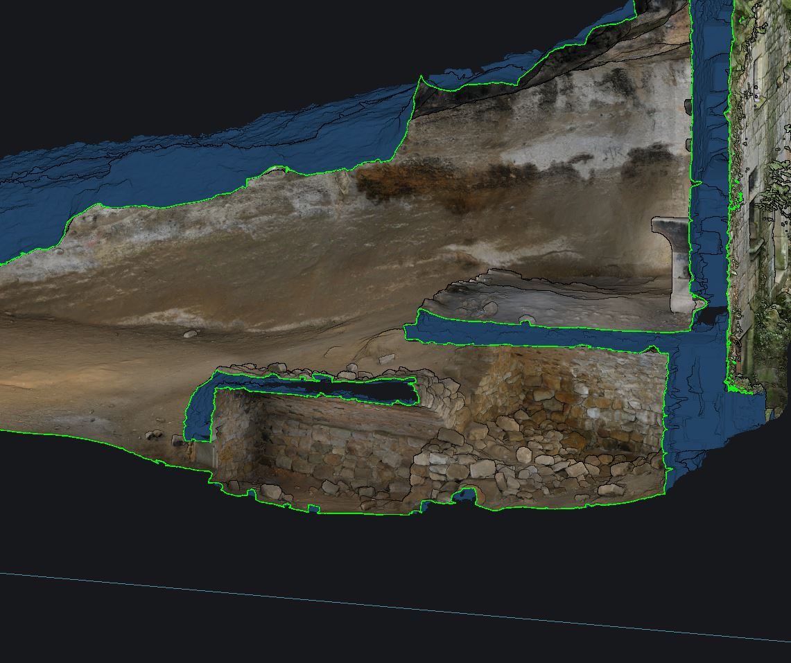
The section plane placed on the model: in blue the material it cuts through, in green the section line.
Step 2
Placing the views
The section plane placed on the model: in blue the material it cuts through, in green the section line.
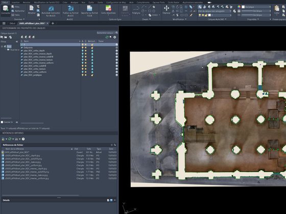 Step 3
Export and check
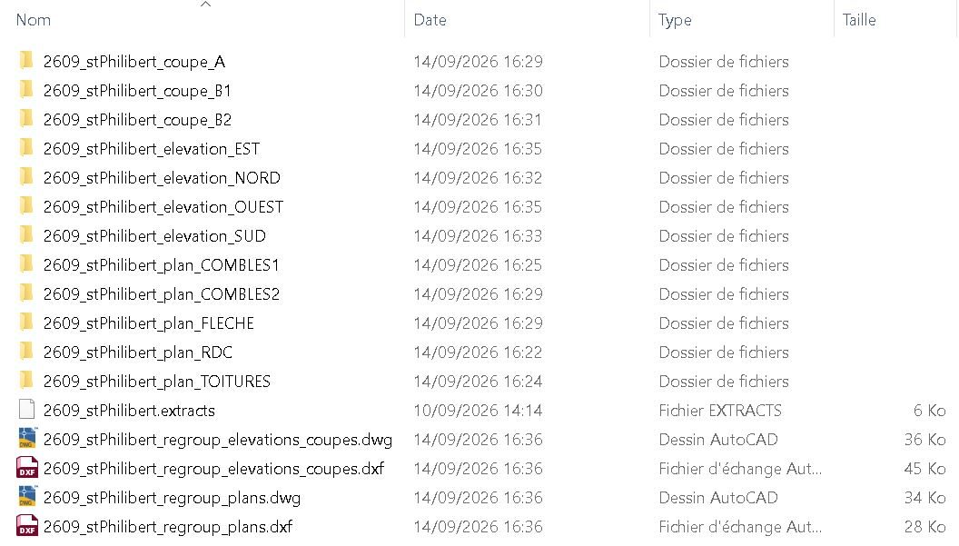
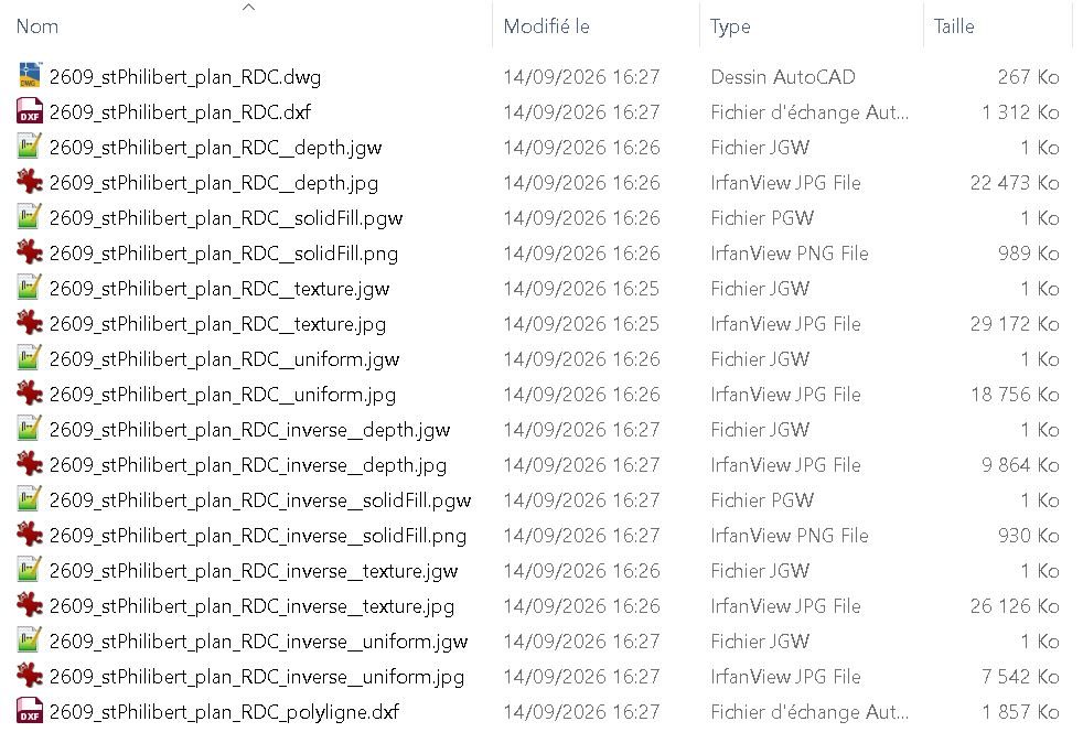
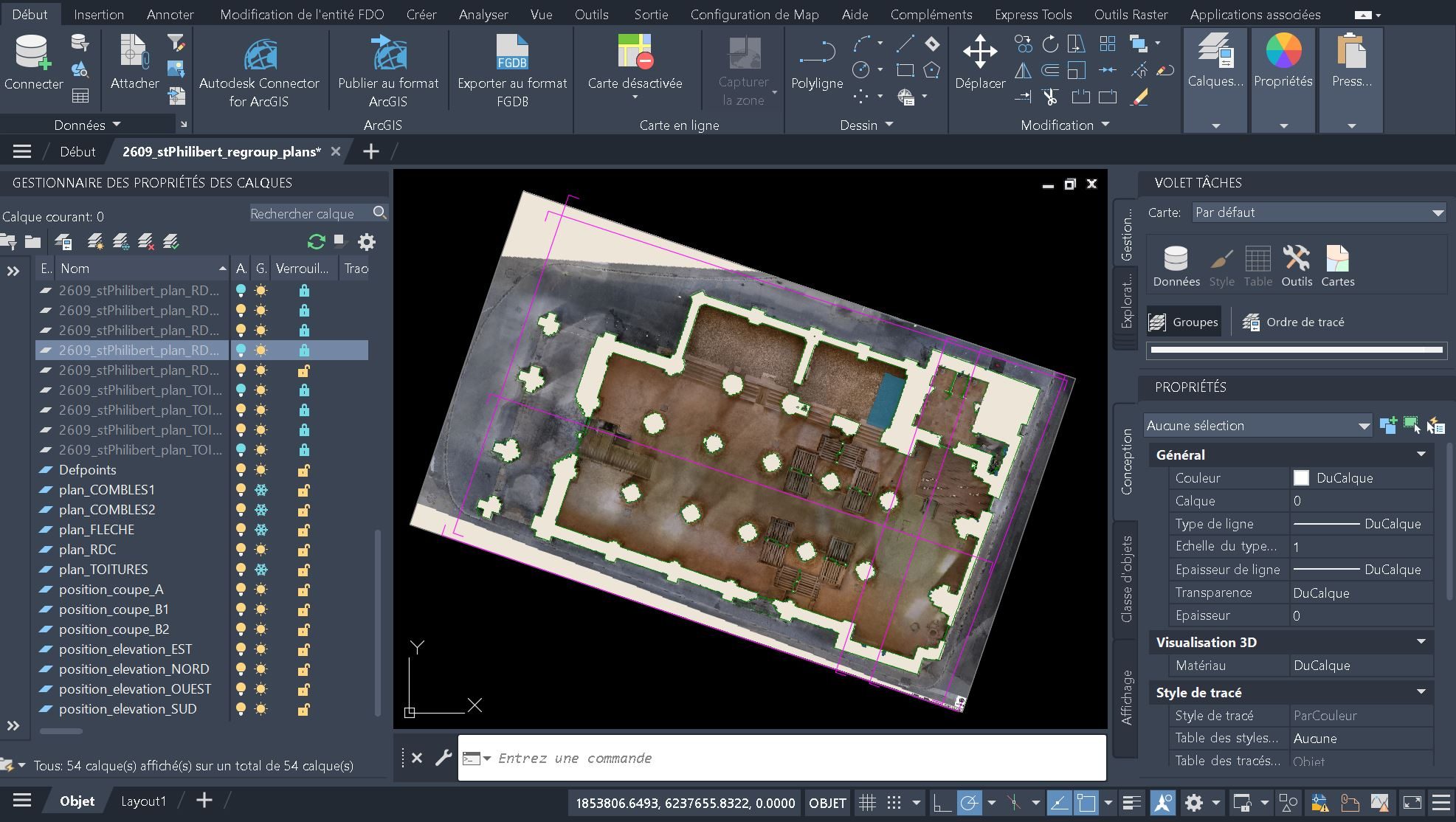
The exported files, named, in one folder per view; the drawing opens framed in AutoCAD.
Step 3
Export and check
The exported files, named, in one folder per view; the drawing opens framed in AutoCAD.
More details
Saving and loading extraction projects
All the views of a project — center, orientation, frame,
resolution, output settings — are saved in an
.extracts file, which can be reloaded to pick the
project up where it left off.
Orthoimage positioning in coordinates
Each image comes with its world file (.jgw,
.pgw).
Guided naming convention
The folder, files and layers are derived automatically from the project name and the view name. Extractions made in several goes, or over several surveys, follow the same rule.
Step 1: Visualization and analysis of 3D models (meshes, point clouds, 3DGS)
Before extraction, the survey is checked on three points: precision, accuracy and sharpness. The analysis tools cover renderings, noise, density, slopes, face orientation and clipping.
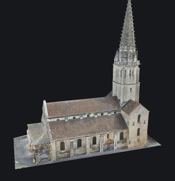
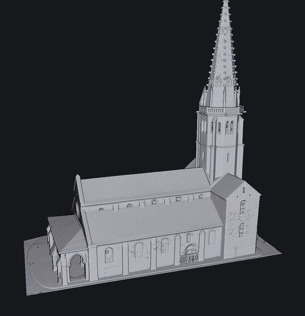
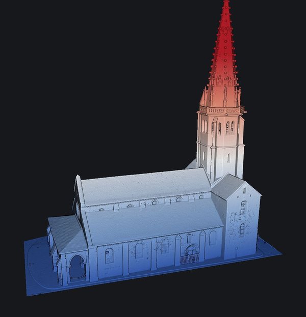
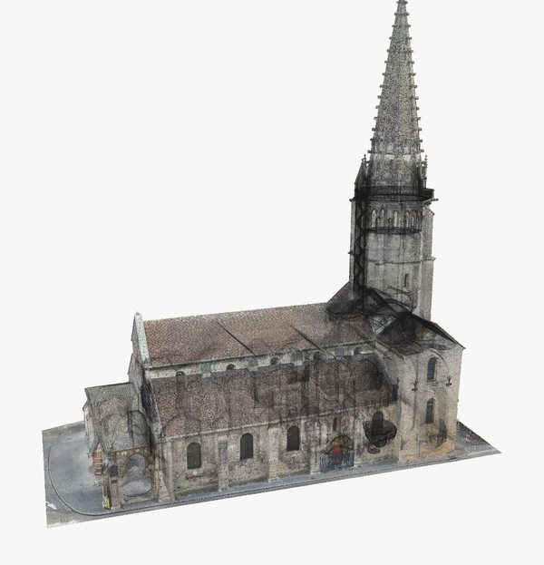
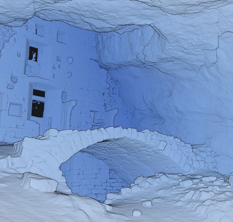
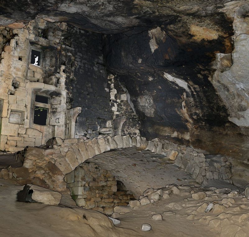
Multi-rendering display of 3D models
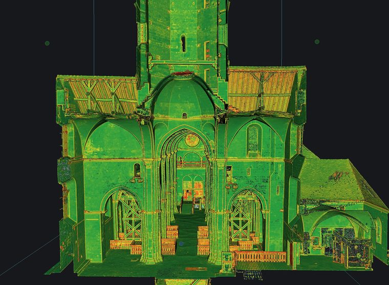
3D model assessment (noise, density, slopes, orientations)
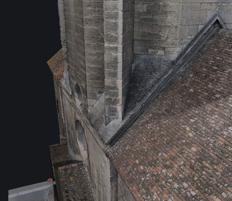
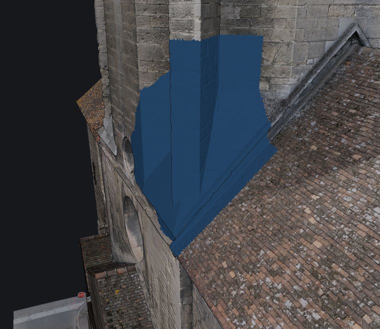
Fixing face orientation errors in the 3D model
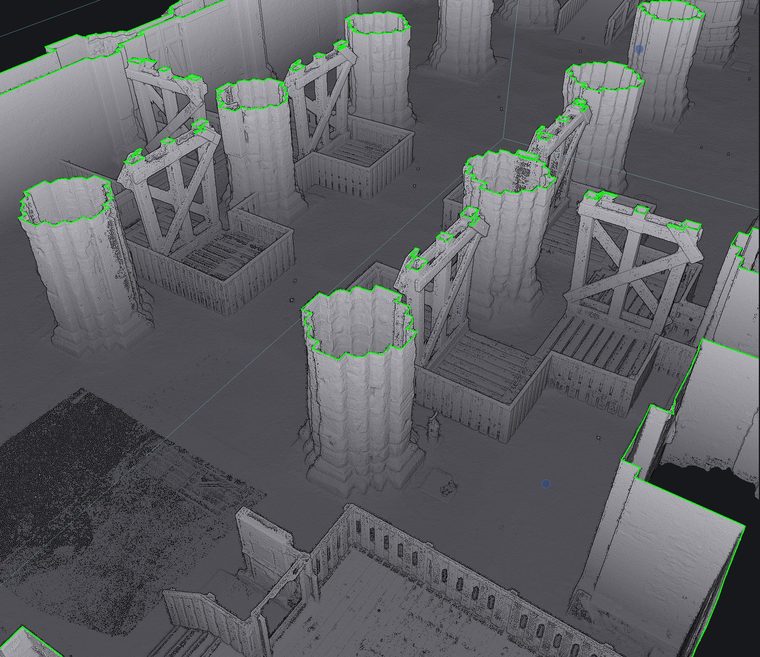
Analysis with the clipping box, section line and export of cloud extracts
Step 2: Four standardized view types
Four view types: plan, inverse plan, section and elevation. Each one is set in the 3D view: center, azimuth, width, height, depth and output resolution.
| Type | Looking | What it is |
|---|---|---|
| plan | downward | roof plan, floor plan, ground floor |
| inverse plan | upward | ceiling plan, roof framing plan based on the associated plan view |
| section | horizontal, through the material | the architect's section |
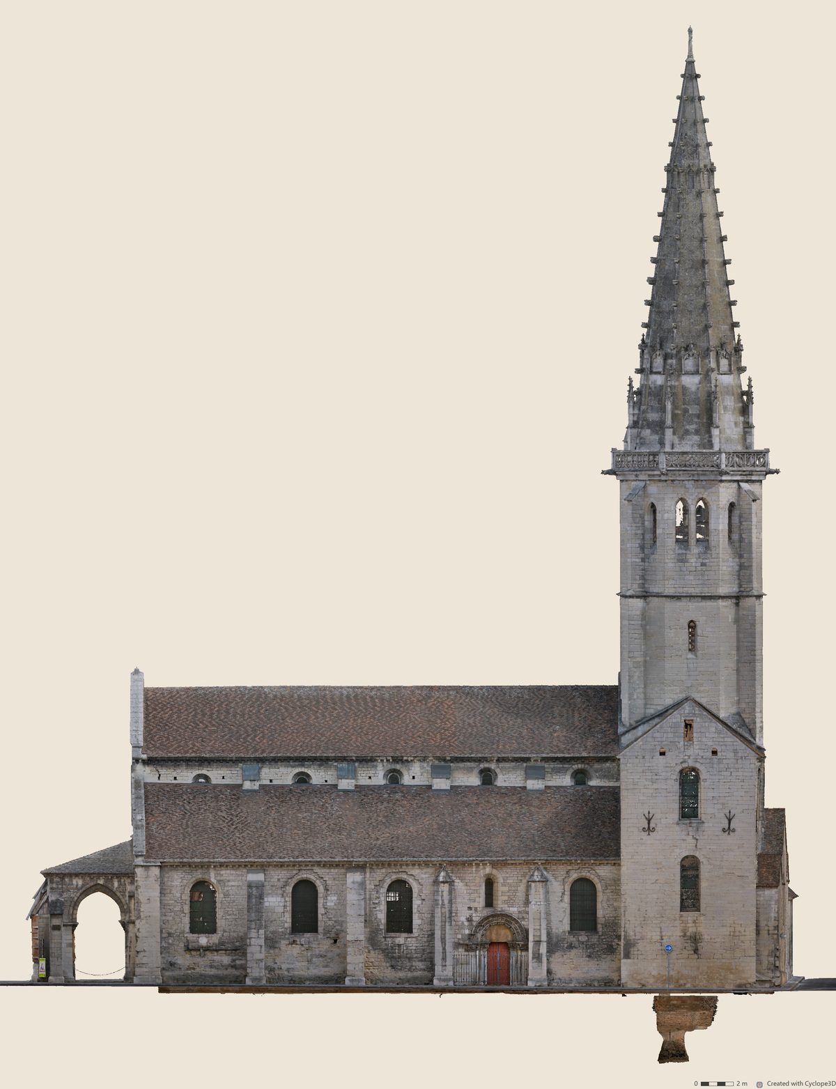
| elevation | horizontal, from outside | a facade |
Automatic export of every representation for each view
Each view comes out in several overlaid representations: texture, geometry, depth, solid areas, X-ray, contours, and custom representations such as height or normals. All of them are included in the drawing output, georeferenced.
Details
Orthoimage background
Color of the pixels that nothing covers in the orthoimage. By default, the cream of the 3DR chain (237, 229, 216), adjustable.
The company logo in the corner of the orthoimages
Optional: the company logo, placed in a corner of every orthoimage.
Automatic tiled orthoimage generation
For surveys of large extent or high resolution, the orthoimage is split into tiles, assembled in a single drawing output.
Vectorized section line generation (meshes and point clouds)
The section line is included in the DWG drawing output, overlaid on the orthoimages. Taken from a point cloud, it carries a confidence level per segment, from green to red.
Step 3: One drawing output per view, the groupings and the view positions
One export folder per requested view: the positioned orthoimages, with their section line. At the root of the output folder, the grouping projects and the view position files.
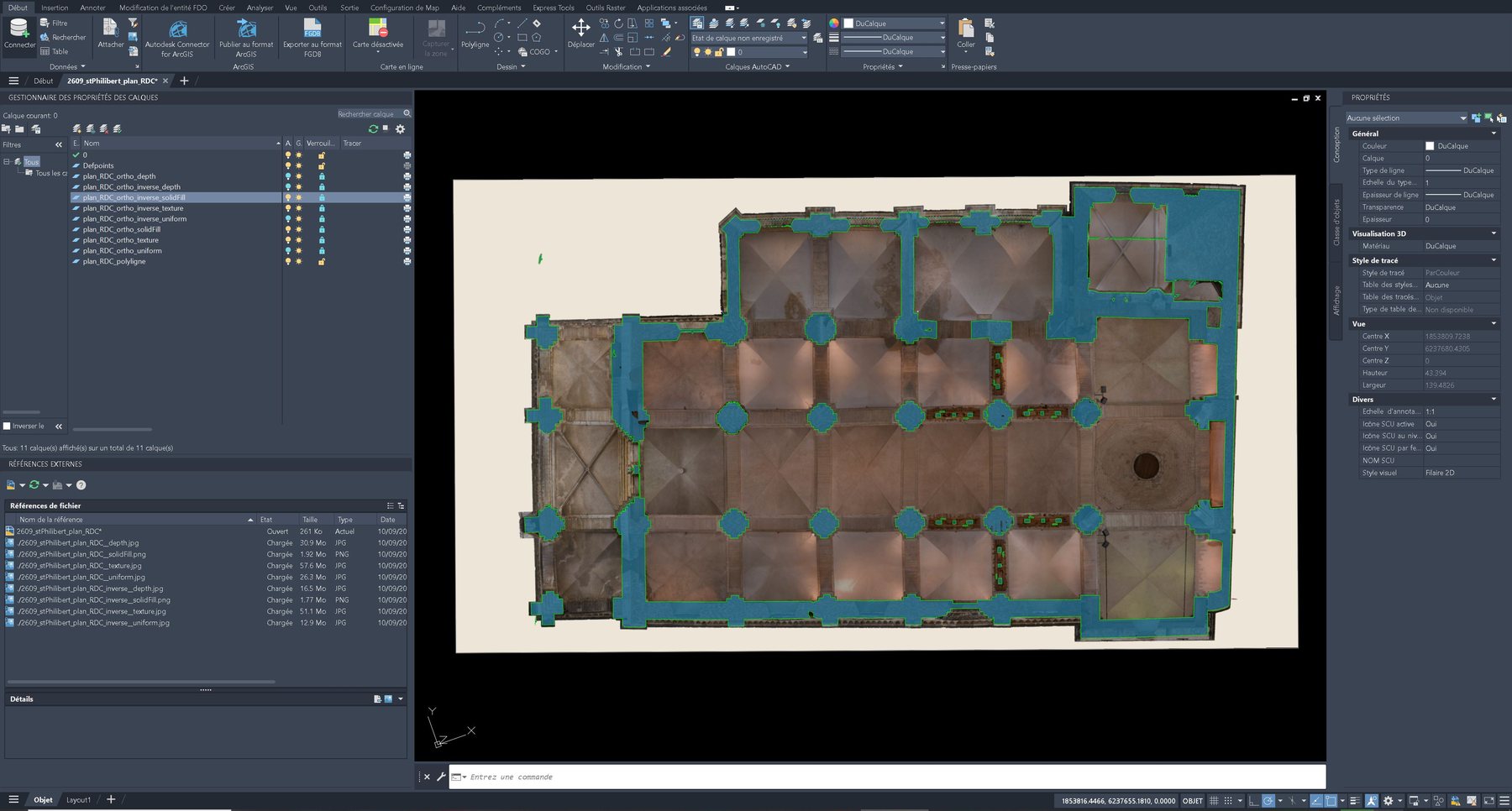

One DXF/DWG per view
Each view includes all the registered representations, with their polylines and layers.
The grouping and view position DWG files
Two .dwg files at the root of the extractions folder:
one calls all the plans, the other the elevations and sections, as
external references. Each view comes in on its own
layer, named after it: the ground floor, upper floor and
roof stack up in one file and are turned on one at a time. No image
is embedded, only links.
A guided naming convention
One folder per view, named
<project>_<view_type>_<view_name>, and every
file prefixed the same way. The names are derived from the project and view names: none is typed by hand, and several surveys follow the same rule.
Details
2608_Abbaye/
  2608_Abbaye_elevation_SUD_OUEST/
    …_SUD_OUEST__texture.jpg                 texture
    …_SUD_OUEST__texture.jgw                 its registration
    …_SUD_OUEST__uniform.jpg                 geometry
    …_SUD_OUEST__depth.jpg                   depth
    …_SUD_OUEST__solidFill.png               solids
    …_SUD_OUEST_polyligne.dxf                the line alone
    …_SUD_OUEST.dxf                          the drawing
    …_SUD_OUEST.dwg                          the same, converted
  2608_Abbaye_plan_RDC/                      the same eight
  2608_Abbaye_plan_TOITURE/                  …
  2608_Abbaye_coupe_A/                       …
  2608_Abbaye_regroup_plans.dwg              the plans, as xrefs
  2608_Abbaye_regroup_elevations_coupes.dwg  elevations and sections, as xrefs
View positions
The grouping projects automatically include layers positioning the project's sections, plans and elevations.
A real example: the Saint-Philibert church by Geokali
15minof automatic export at 3 mm/pixel (2 min at 1 cm/pixel)
- 12views5 plans, 3 sections, 4 elevations
- 56orthoimagesin 4 variants: texture, geometry, depth, solids
- 12view DXF/DWG/PDF filesregistered images, polylines and layers
- 2grouping DWG filesthe plans, then the elevations and sections
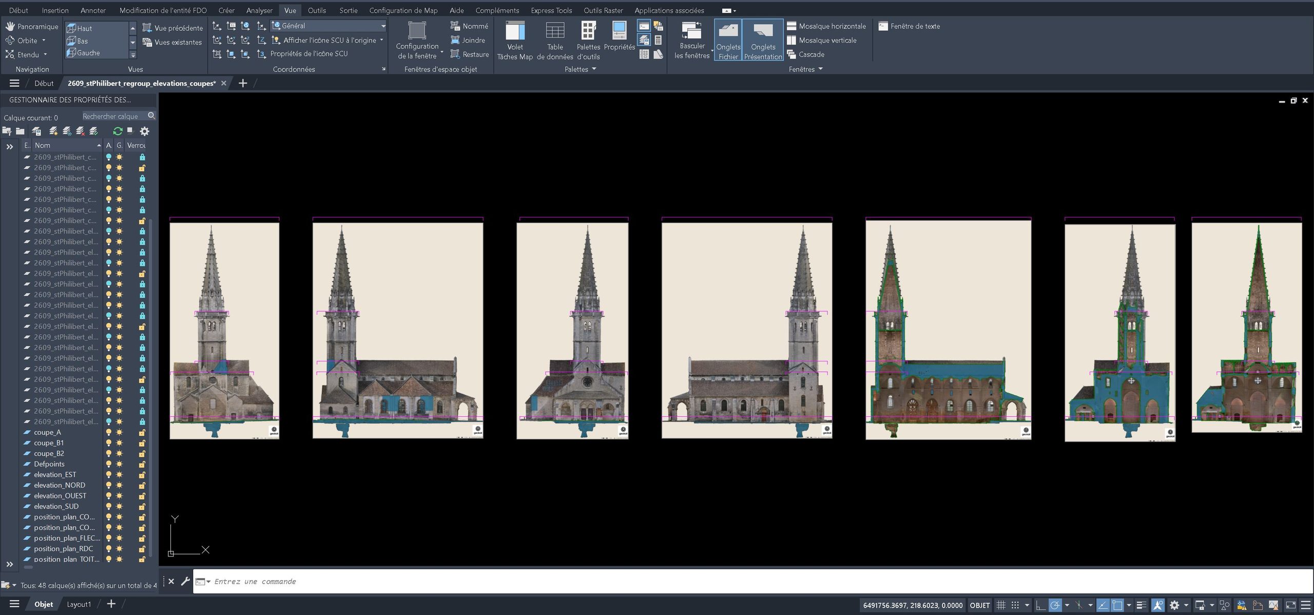
Data courtesy of GeokaliFiles exported by Cyclope3D, with no manual retouching
Browse the delivered filesA real example: the C12 high school (VLX point cloud and drone mesh), with section variants 15 views · 45 orthoimages · 2 cm/pixel
- 15views1 plan, 10 sections, 4 elevations
- 45orthoimagesin 3 variants: texture, geometry, depth
- 15view DXF/DWG/PDF filesregistered images, polylines and layers
- 2grouping DWG filesthe plans, then the elevations and sections
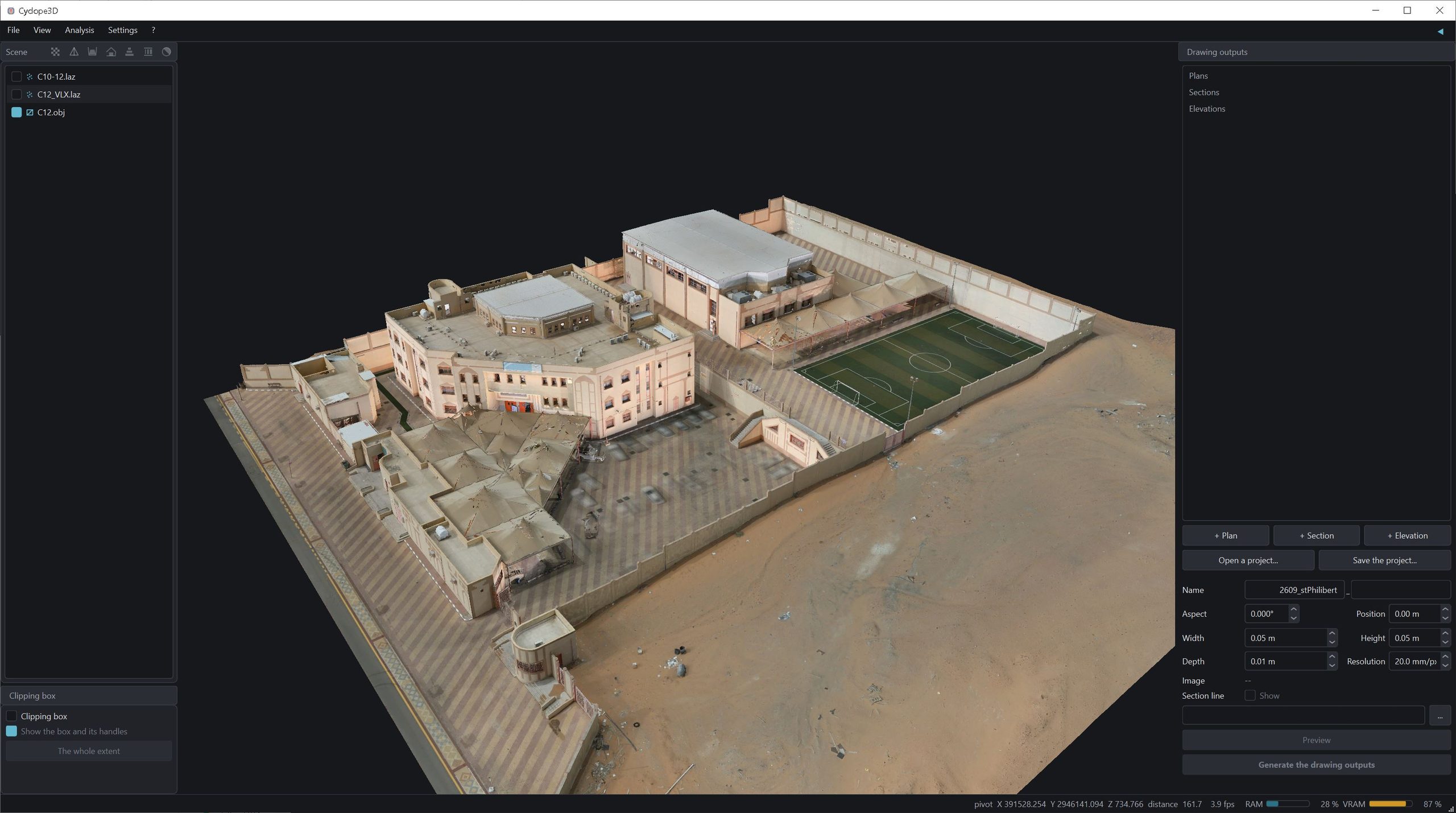
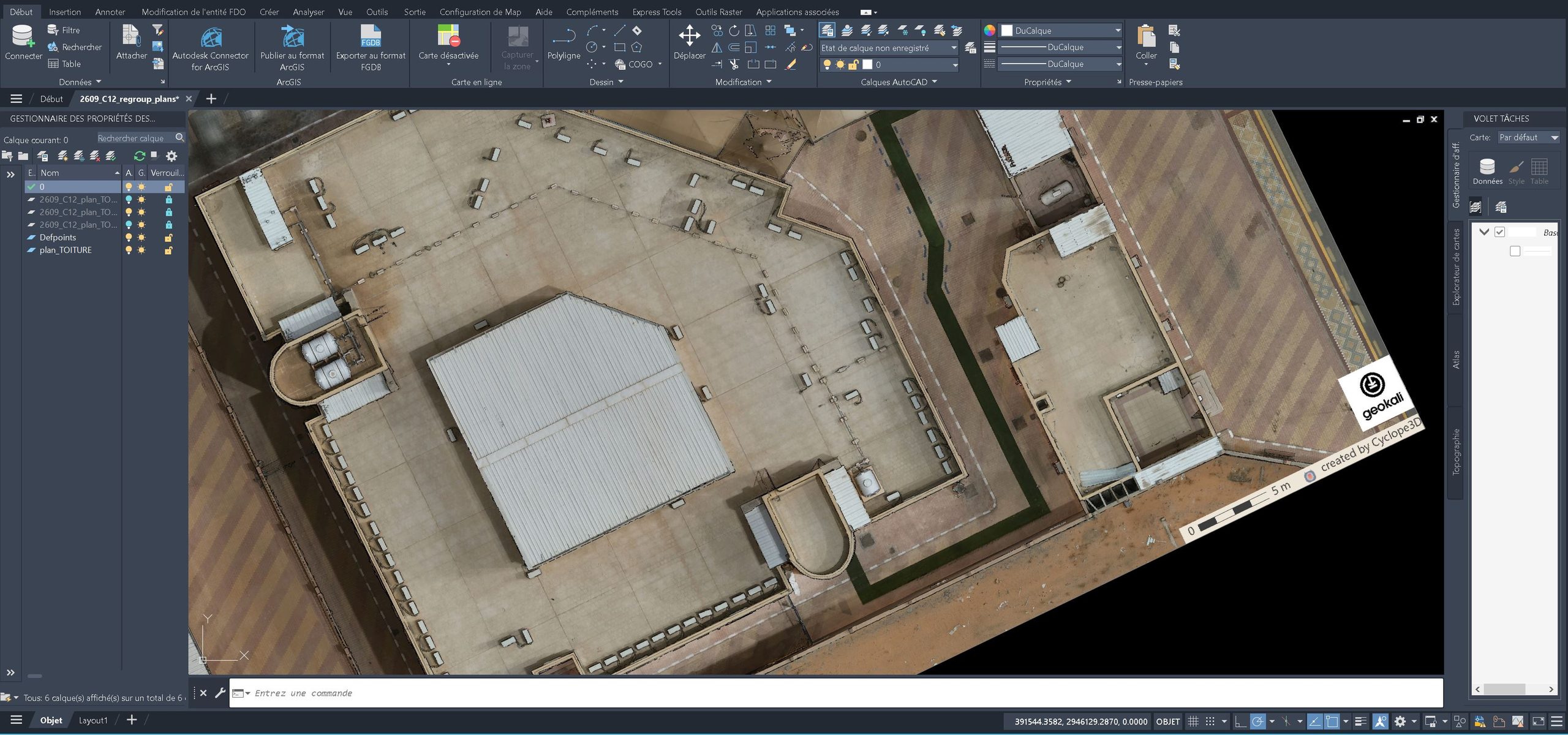
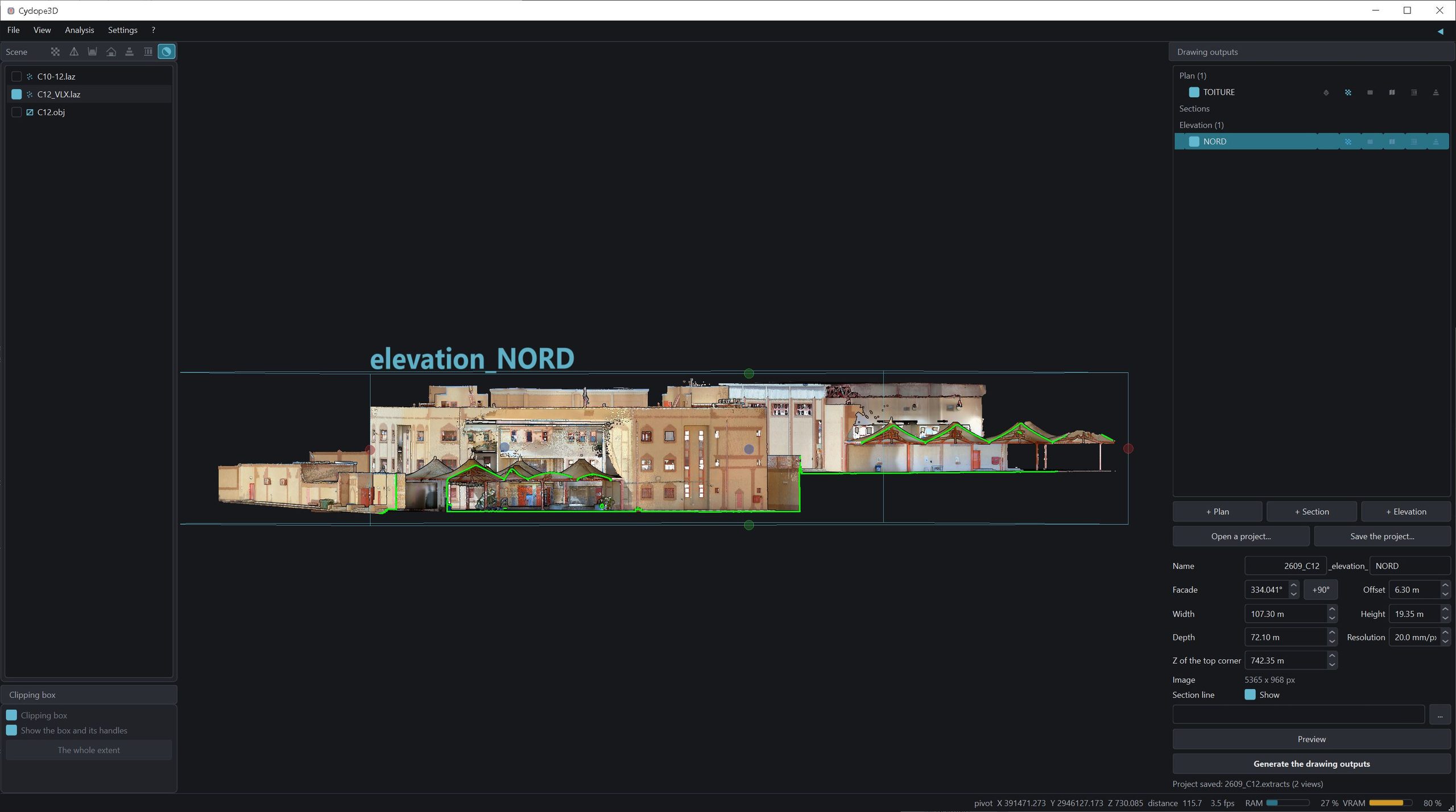
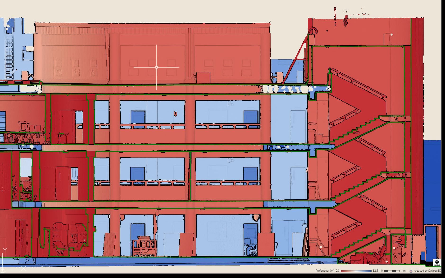

Data courtesy of Geokali
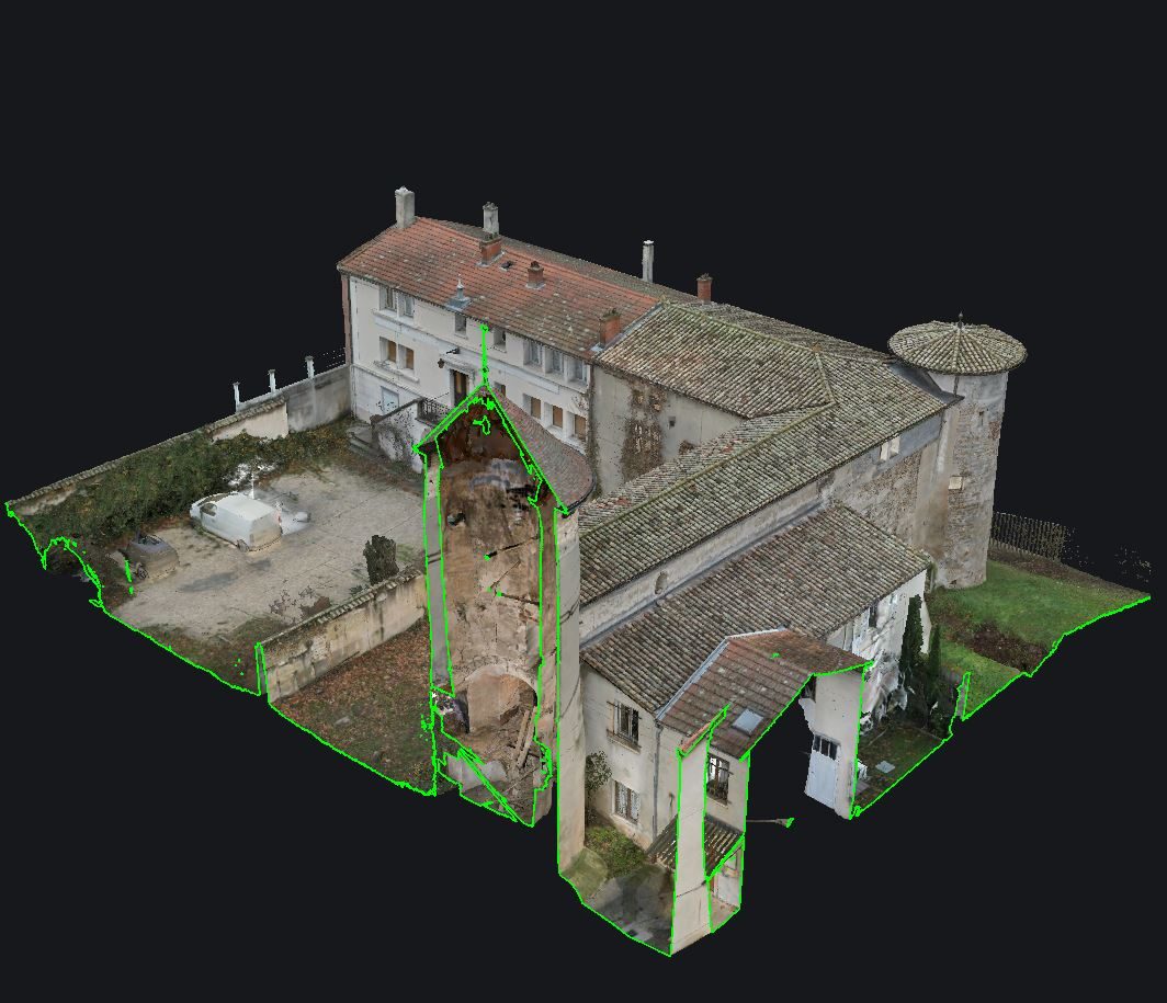
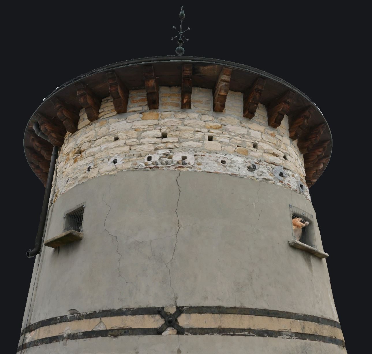
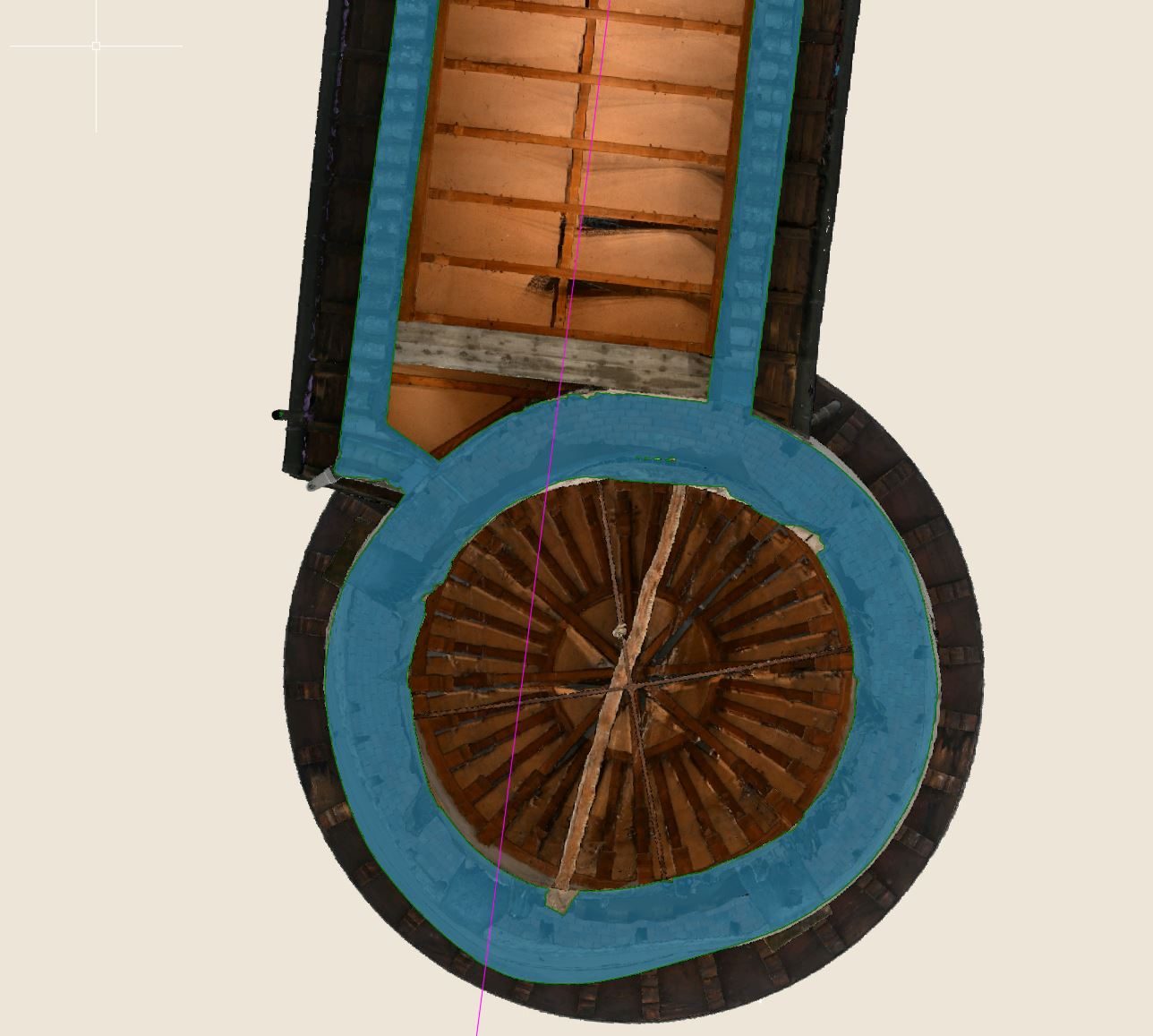
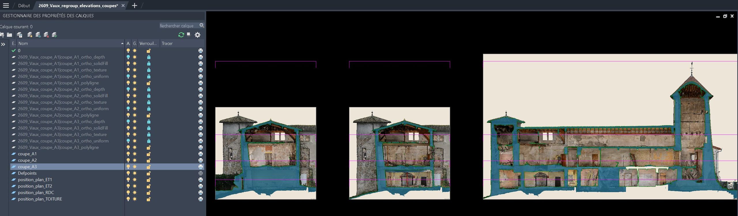
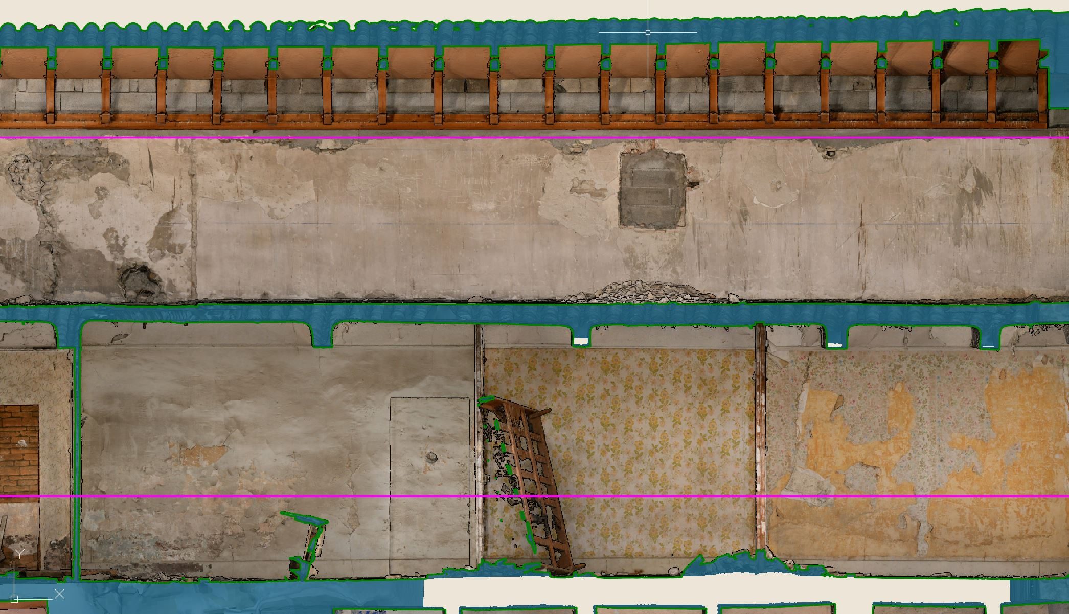
A real example: the Vaux project (mesh) 4 min · 7 views · 41 orthoimages · 5 mm/pixel
4minof automatic export at 5 mm/pixel
- 7views4 plans, 3 sections
- 41orthoimagesin 5 variants: texture, geometry, depth, solids, X-ray
- 7view DXF/DWG/PDF filesregistered images, polylines and layers
- 2grouping DWG filesthe plans, then the elevations and sections
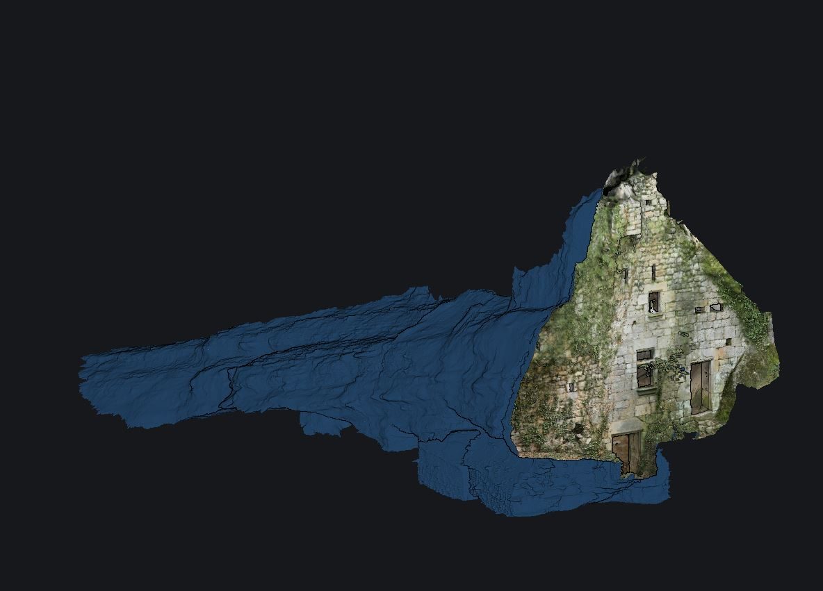
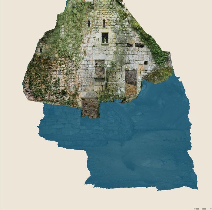
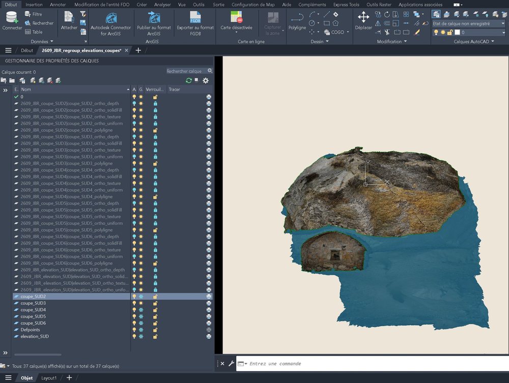
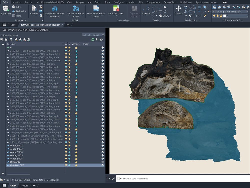
A real example: the JBR project (mesh) 9 min · 6 views · 24 orthoimages · 2 mm/pixel
9minof automatic export at 2 mm/pixel
- 6views5 sections, 1 elevation
- 24orthoimagesin 4 variants: texture, geometry, depth, solids
- 6view DXF/DWG/PDF filesregistered images, polylines and layers
- 1grouping DWG filethe elevations and sections
A real example: Notre-Dame de Dijon (mesh) 140 M triangles · 15 views · 71 orthoimages · 3 mm/pixel
140milliontriangles and 97 16K textures, extracted at 3 mm/pixel
- 15views8 plans, 3 sections, 4 elevations
- 71orthoimagesin 4 variants: texture, geometry, depth, solids, and 7 plans also seen from below
- 15view DXF/DWG/PDF filesregistered images, polylines and layers
- 2grouping DWG filesthe plans, then the elevations and sections
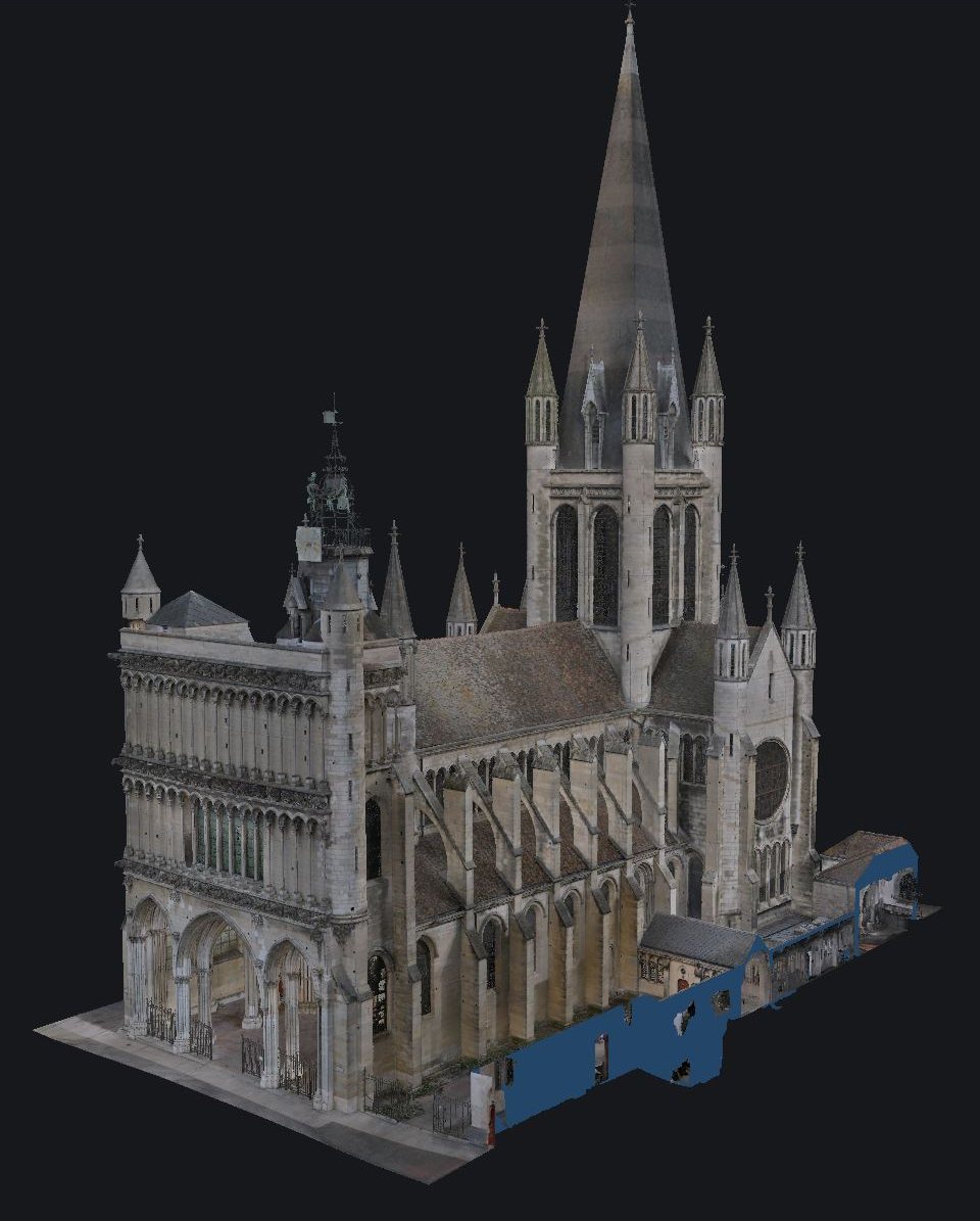
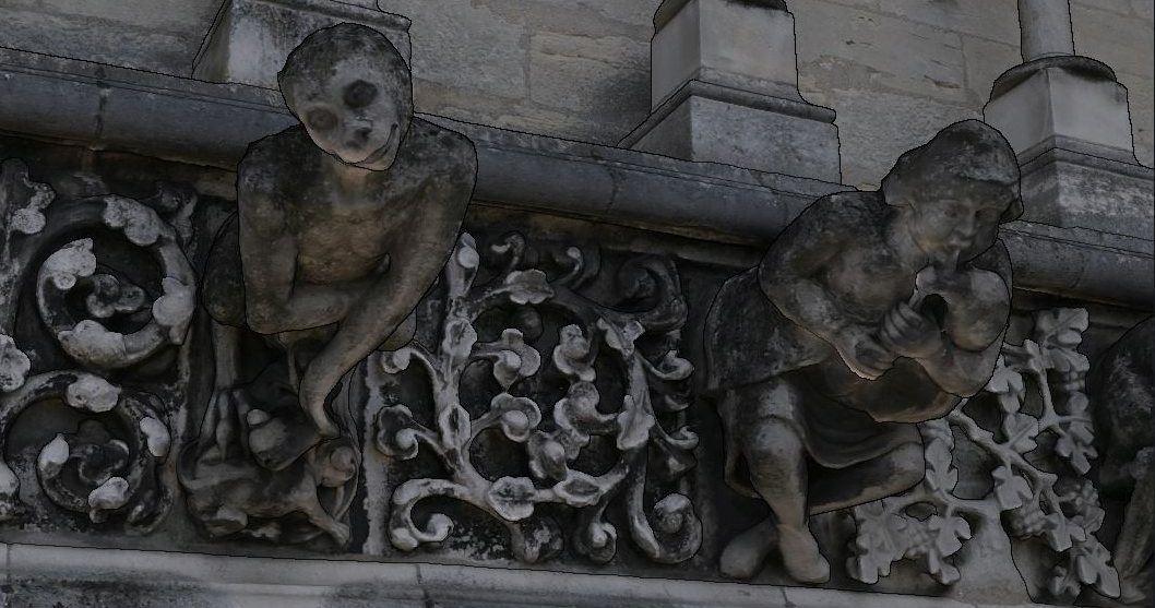
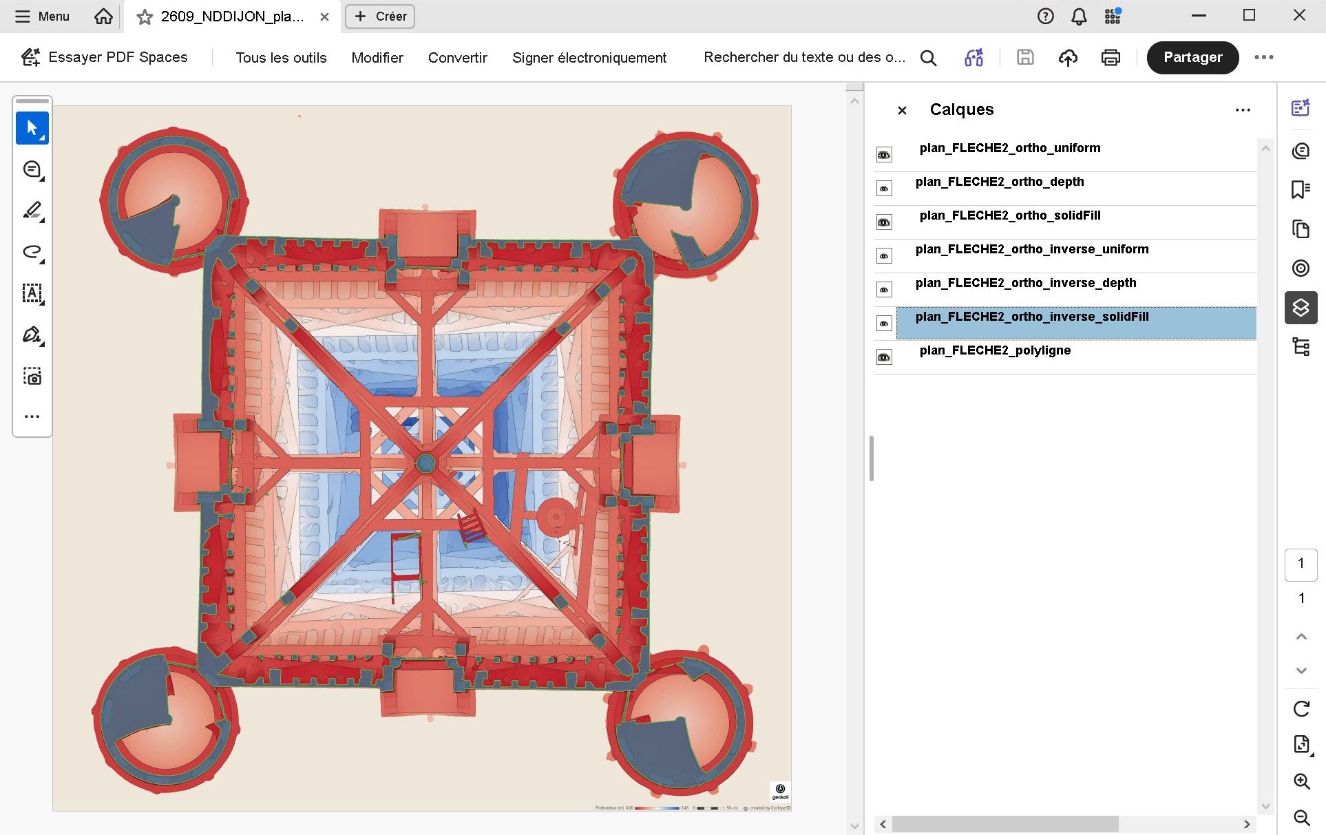
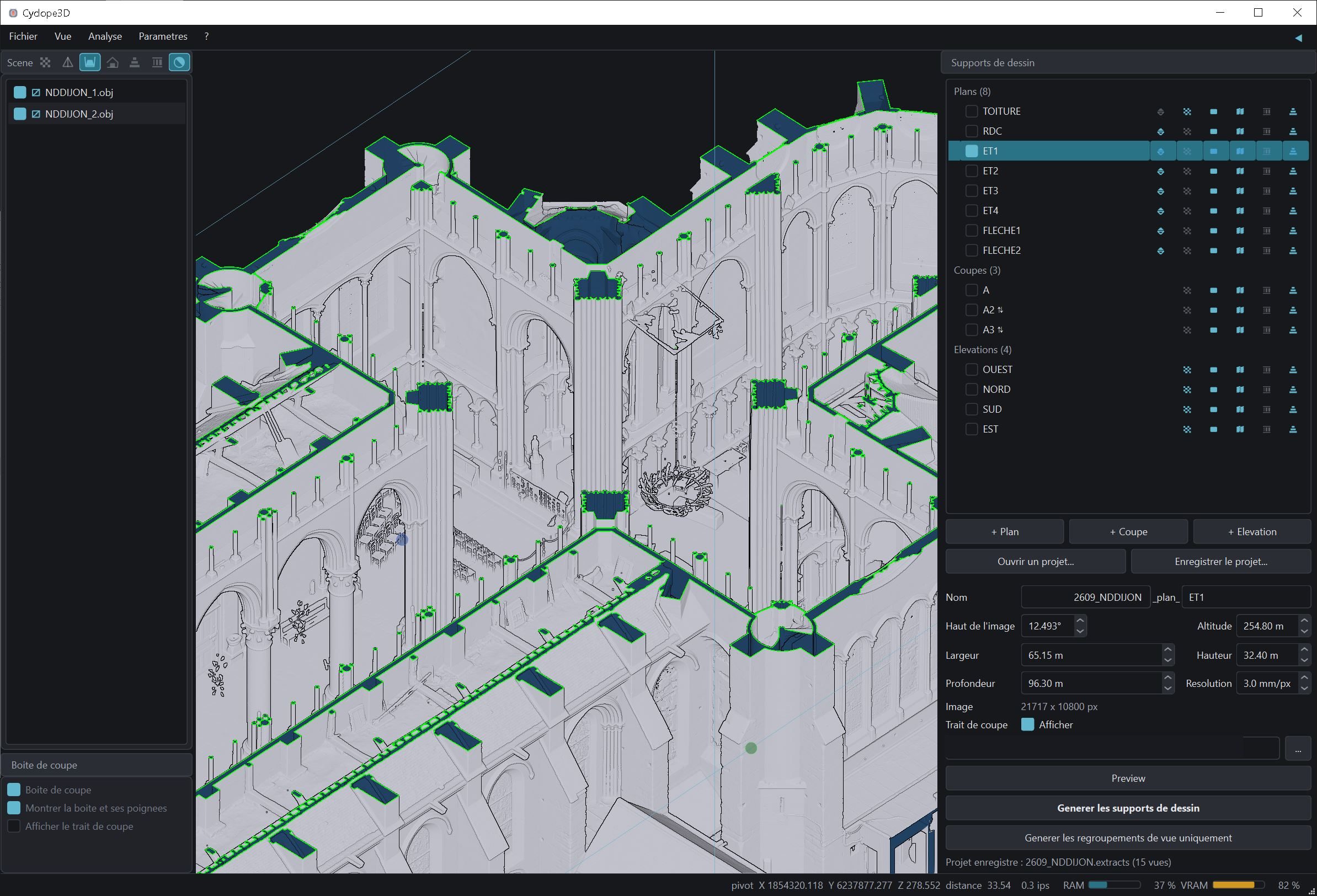
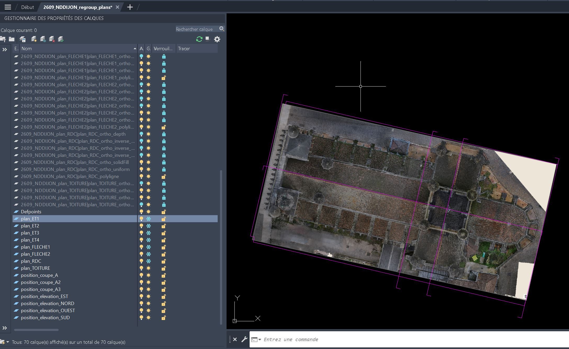
Data courtesy of Geokali, digitization project of the Notre-Dame de Dijon churchResources used: 70 GB of RAM and 10 GB of dedicated video memory, generation in 1 h 30 min
Partners
Cyclope3D was built with specialists in surveying, heritage technical drafting and the management of historic monuments.




System requirements
- Windows 10 or 11, 64-bit.
- 16 GB of RAM or more.
- Dedicated graphics card.
- No installation required.
- Model import:
- Point clouds: .LAS / .LAZ / .E57 / .PLY
- Meshes: .OBJ
- 3DGS: .PLY
Optimization of PC resource needs
Textures loaded according to the viewpoint, computation spread over every processor core, orthoimages computed on the NVIDIA graphics card (CUDA).
Access to the software
Cyclope3D is in free early access for 6 months, with no commercial restrictions. It is used every day on production surveys. The changes under way are listed in the roadmap below.
License key and download
Please contact me via LinkedIn to get a license key: direct support, feedback, new features and customizations.
Under study
The changes under study, and those already delivered. Feedback from use adds to the list.
-
Point clouds
Support for point clouds of several billion points
-
Point clouds
Point cloud reduction
With export of the reduced cloud.
-
3D models
Export of 3D models after analysis
The fields computed by the Analysis menu (noise, slope, face orientation), exported with the model.
-
3D models
Extraction of 3D sub-models
-
3D models
Fine, clean cutting of models
-
Navigation
3D mouse support (3Dconnexion SpaceMouse)
-
Interface
Light theme
-
File formats
3DGS model support
Section line computation, faster rendering, and orthoimage export.
-
Views
Exporting views with scalar representations (classification, slope, height, etc.)
-
Views
Overhaul of the views and renderings system
Several display configurations, saved one per rendering.
-
3D models
Brightness and contrast control of 3D models before export
-
3D models
Sharpness adjustment
-
Point clouds
Orthoimage processing time divided by 7 (graphics card, CUDA)
-
Views
X-ray rendering for all 3D model types, on light and dark backgrounds
-
Analysis
Face orientation computation for point clouds and 3DGS
-
Orthoimages
Cylindrical and conical unrolling
-
Performance
Handling of 3D model levels of detail (LOD) and point cloud octrees
-
Measurements
Coordinates, distances, areas, volumes
Measurements taken in the 3D model, without going through the drawing.
-
3D models
PDF report on accuracy and information
Accuracy and contents of the survey, on one page attached to the delivery.
-
Deliverables
Advanced customization of exports
Naming, colors, positions, theme and margins, set once for the whole delivery.